
Blood Slide Stainer Main Control Board
The main board of a laboratory blood slide stainer, driving the pump, electromagnet, fan and Peltier loads from a single controller. Three switching regulators distribute 12 V, 5 V and 3.3 V from one input; the control and load sides are separated by optocouplers.
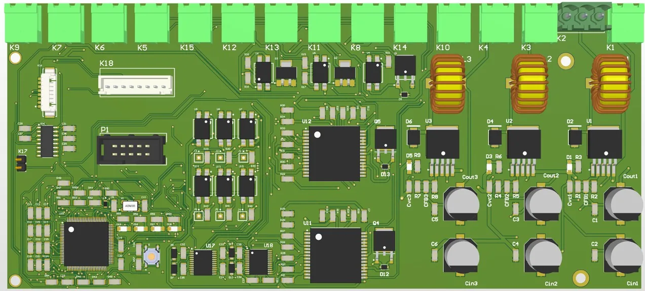
The board was designed to control every actuator and sensor of an automated blood slide stainer from a single point. The pump motors, rack and drawer locks, fans and a Peltier cooler are all driven from this board. Signals between the controller and the high-current loads are separated with optocouplers. The connection terminals run along the top edge of the board; the power input and regulators sit on the right, the motor and electromagnet drivers in the middle, and the controller in the lower-left corner.
Architecture
- Controller
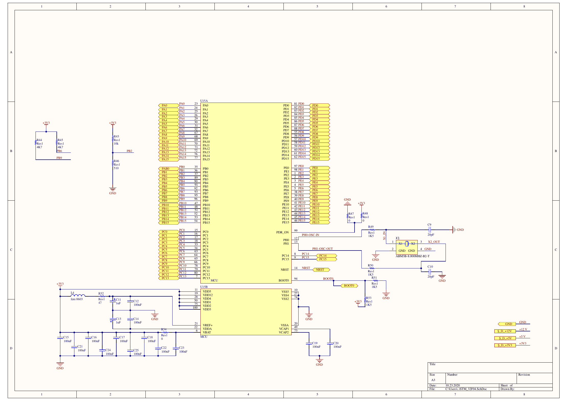
- STM32F4-series microcontroller (LQFP100), 8 MHz crystal, SWD programming header and reset/BOOT0 circuitry.
- Power distribution
- Three XL4015 switching buck regulators derive the 12 V, 5 V and 3.3 V rails from a single terminal input; each rail has an indicator LED.
- Pump motors
- Two VNH2SP30 full-bridge motor drivers and IRFR3707Z MOSFET switches for the distilled-water and waste pumps.
- Electromagnets
- Two TB6612FNG drivers for the rack and the right and left drawer locks, with Schottky diode protection on the coil terminals.
- Fans and Peltier
- The 12 V rack and filter fans are driven by BCP56 transistors and the Peltier module by a MOSFET; every control input goes through an optocoupler.
- Sensors
- Level, waste and distilled-water sensor inputs, plus a 12 V voltage divider for the capacitive sensor.
- Communication and interface
- An RS-232 line via MAX3232, four status LEDs and optocoupled 3.3 V–5 V control outputs for auxiliary motor boards.
Images
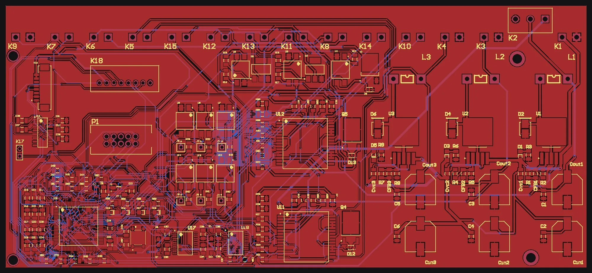
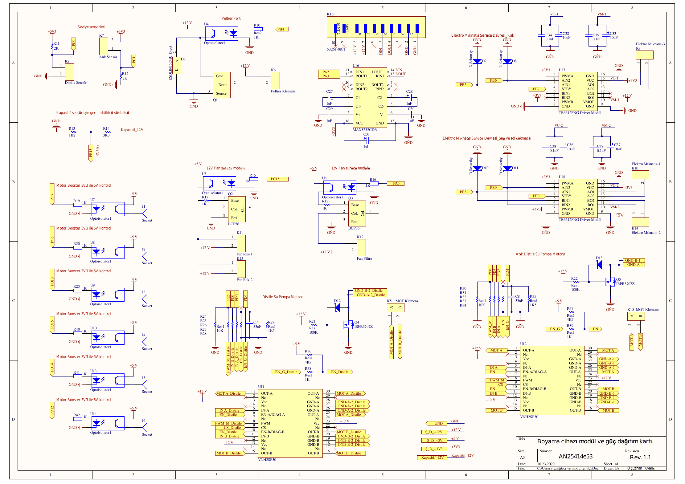
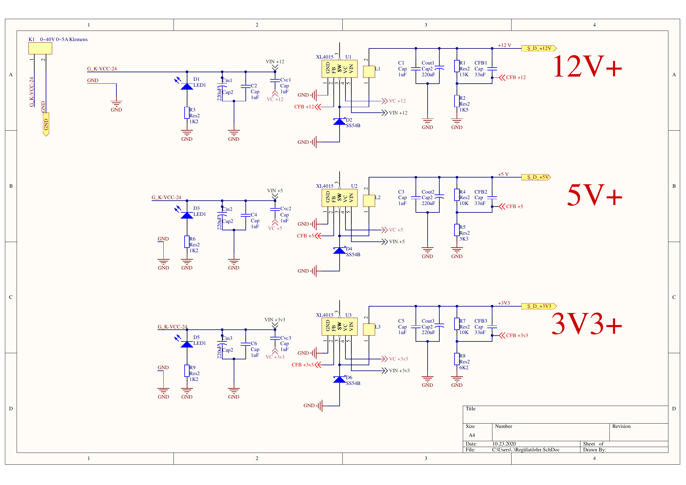
Let's talk about your project
Tell us about your hardware need or R&D idea, and we will clarify the scope and the steps together.